Design of Remote Meter Reading System Based on CAN / RS485 Double-layer Network 1 Introduction At present, the metering instruments used by users, namely water meters, electricity meters, gas meters, and heat meters (four meters) are generally installed in the user's room. The meter reading staff walks from house to house, manually reading the meter to collect data, and then billing. In order to effectively solve the many disadvantages of meter reading charges for households, China has been developing all-electric energy meters since the early 1990s, and has achieved certain results. At present, a variety of remote meter reading systems have been developed. Commonly used meter reading systems based on power line carrier, meter reading systems based on RS-485 bus, etc. Start of frame: 1 significant bit, marking the start of the frame. The main monitoring program decides whether and to whom the data is sent based on whether there is a message in the receiving buffer. If there is a message in the CAN subnet data buffer, it will be forwarded to the RS-485 subnet, and if there is data in the RS-485 subnet data buffer, it will be forwarded to the CAN subnet. Because the frame format length of the CAN message and the custom RS-485 message are different, the frame format conversion is required when forwarding the message. After forwarding the message, it is necessary to adjust the parameters of the corresponding FIFO buffer. In addition, in the main monitoring program, if the host computer has a status request to the bridge or the bridge itself is faulty, the bridge can return to the host computer status. This function is convenient for system fault location. The computer of the management center can find system faults in advance by running remote meter reading management software, which enhances the maintainability of the system. Active Professional Ktv Speaker,Top Speakers For Live Performance,Top Professional Performance Speakers,Portable Performance Speaker NINGBO RFUN AUDIO TECHNOLOGY CO.,LTD , https://www.mosensound.com
The meter reading system based on the power line carrier reduces the cost of the system due to wiring, but because the signal and strong electricity are transmitted on the same line, there is inevitably interference from the strong electric field during the transmission process, and the reliability of the signal is affected. And as the transmission distance increases, the signal attenuation is faster, which affects the reliability of meter reading data; the meter reading system based on RS-485 is an ideal remote meter reading system, which uses a master-slave type Only one node is allowed to send data to the network at any time, so RS-485 mostly uses the command-type communication method of the master-slave structure to prevent data communication failure. The master node must receive the command of the management host during data communication, and then The master node transmits commands to each slave node, the data of the slave node is sent to the master node in turn, and finally the master node sends the data of each slave node to the management host. It can be seen from the data communication process that if the master node fails, the entire system will fall into a paralyzed state. In addition, with the continuous expansion of users in residential areas, the field data communication distance of the meter reading system is also required to increase. Since the maximum transmission distance that can be achieved at 9600 bps using the 485 bus is less than 1200 meters, one or more additional Relaying to achieve the remote transmission and reception of data. Because 485 is half-duplex communication, the repeater must judge the network data flow direction during work, so the structure of the repeater is complicated, resulting in increased system cost and reduced system reliability.
CAN (Controller Area Network) is short for Controller Area Network. It is a serial data communication bus developed by German Bosch company in 1986. The nodes on the CAN network are not divided into master and slave. Any node can actively send information to other nodes on the network at any time. The communication method is flexible. This feature can easily form a multi-machine backup system. CAN uses non-destructive Bus arbitration technology, when multiple nodes send information to the bus at the same time, the node with lower priority will quit actively, and the node with the highest priority can continue to transmit data without being affected, thereby saving the arbitration time of bus conflicts.
According to their respective characteristics, we adopt the CAN bus technology that conforms to the international standard ISO 11898 and the current RS-485 bus commonly used in instruments and automation devices to form a double-layer network structure. This network structure effectively solves the high construction cost and data of the system. Problems such as difficult management, low reliability, and poor scalability.
2. The overall design framework of the system The system uses a double-layer network architecture, see Figure 1. 
At present, China's four meters are generally installed indoors, and the working environment is not bad, so the low-level network of this system uses RS-485 bus. It has the characteristics of simple structure, low cost, and low wiring requirements; and the maximum transmission distance of RS-485 bus at 9600bps can reach 1200 meters, which can completely complete the distance of remote communication between the home controller and centralized controller of a building Demand; coupled with the small amount of communication data between them, the data structure is simple, so the RS-485 bus can reliably complete the needs of low-level data collection. The high-level network adopts the CAN bus with good compatibility, high reliability, fast data transmission speed and long transmission distance (the transmission distance is 10km at 5000bps). The CAN bus adopts short frame structure, short transmission time, low probability of interference; has CRC check and error calibration capabilities; and has the function of automatically disconnecting the faulty node from the CAN bus, etc. It is particularly suitable for centralized control in harsh environments and frequent data exchange Between the computer and the management center computer.
The system consists of a household controller, a centralized controller, and a host of the management center to form a two-level distributed monitoring system. The home controller uses a single-chip microcomputer as the core, can receive the pulse signal sent by the energy consumption meter (four meters), and performs functions such as counting, data processing, saving data, sending user information, and displaying user status information. To improve reliability, it is equipped with Independent backup power supply. The centralized controller can centrally manage a certain number of home controllers and transfer the data collected by each home controller to the management center. At the same time, in order to ensure the safety of user information, the collected data is backed up. It also has a backup The power supply can continue to supply power to the controller during a power outage. In general, a building is equipped with a centralized controller. The host of the community management center runs the remote meter reading management software to process the data information transmitted by the lower computer, such as statistics, payment management, reports, network accident alarm and other operations. In order to reduce the design cost of the system, both RS-485 and CAN use inexpensive twisted pair connections.
3. CAN bus communication protocol
3.1 Levels on the CAN bus
The CAN bus has two logic states: recessive or dominant. In the recessive state, VCANL and VCANH are fixed at the average voltage level, and Vdiff is approximately zero. The dominant state is represented by a differential voltage greater than the minimum threshold.
Display bit (0): VCANH 3.5V, VCANL 1.5V
Hidden bit (1): VCANH 2.5V, VCANL 2.5V
3.2 During bus arbitration and arbitration, each sending node compares its sent bit level with the monitored bus level. Any node that sends a recessive bit and monitors a dominant bit level immediately becomes a receiver Without destroying any information on the bus, wait until the bus is idle, and then resend the message. The lower the binary value of the message identifier, the higher its priority.
3.3 CAN bus message format
The CAN technical specification defines the CAN message format. CAN defines four different frames, data frame, remote frame, error frame, and overload frame.
The composition format of the data frame is shown in Figure 2. 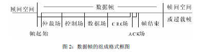
Arbitration field: It consists of a flag and a remote transmission request bit (RTR).
Control field: data length code and two reserved bits.
Data field: including 0 ~ 8 bytes, each byte is 8 bits.
CRC: CRC sequence and CRC delimiter.
Response field (ACK): response gap and response delimiter.
The composition format of the remote frame is similar to the data frame including the start of the frame, the arbitration field, the control field, the CRC, and the response field. In contrast to the data frame, the RTR bit of the remote frame is a hidden bit, and there is no data field in the remote frame.
The error frame consists of two different fields, the first field is obtained by superimposing the error flags from each station, and the second field is the error delimiter.
The overload frame includes two bit fields, overload flag and overload delimiter.
The inter-frame space includes intermittent fields and bus idle fields.
4. Hardware design of centralized meter reading device
4.1 The hardware design of the centralized meter reading device Because the bottom layer uses RS-485, and the upper layer of the network uses the CAN bus protocol, this requires that the centralized meter reading device not only has data acquisition and data backup, but also has a network bridge for protocol conversion. Features. The design principle diagram of CAN and RS-485 bus conversion bridge is shown in Figure 3. 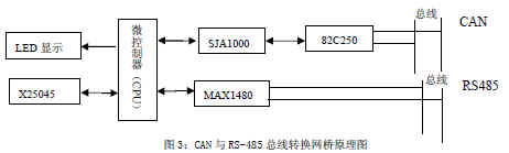
The microcontroller of the bridge uses TI's MSP430F449, which is responsible for the monitoring tasks of the entire bridge. The CAN controller interface circuit is composed of the CAN communication controller SJA1000 and the CAN bus transceiver 82C250. In order to improve the reliability and anti-interference ability of the system, an optical coupling circuit can be added between SJA1000 and 82C250. The RS-485 bus terminal uses a differential transceiver MAX1480 with optical coupling inside. The LEDs designed in the bridge can be used for power-on indication on the bridge, bus transceiver status and fault condition indication. The bridge watchdog uses a piece of X25045. In addition to the watchdog and power-on reset functions, the X25045 also integrates a 512-byte serial EEPROM, which is used to save bridge bridge parameter configuration and other information. The configuration of the network bridge can be achieved through the CAN bus or RS-485 bus, and the appropriate configuration of the network bridge can easily filter the messages.
4.2 Software design of the centralized meter reading device The data reception of the bridge bus adopts the interruption method, and the data is sent in the main monitoring, and the memory is managed by the FIFO mechanism.
Because RS-485 bus and CAN bus are two different bus forms. When communicating with each other, protocol conversion is required. The CAN bus standard has physical layer and data link layer protocols, and performs data communication in units of frames, and each frame carries a corresponding ID identifier, and RS-485 is essentially a physical standard, which performs data in bytes. Communication, without any other auxiliary information, the format is completely defined by the user. So when considering the design of RS-485 frame format, you should refer to the frame format of the CAN bus. When designing the RS-485 frame format, you can refer to the following format: 
The first field is the address field, which occupies one byte and is used as the multi-machine communication address of the RS-485 subnet. In the RS-485 network, only one master and many slaves can be used for communication. There must be one master control node in the network, where the bridge is the master control node, and the communication is carried out by querying the roll call. The second to fourth fields have the same definition as the fields of the same name in the CAN message. In fact, these three fields are a complete CAN message. The network bridge only needs to send the CAN message composed of these three fields when forwarding, so that the protocol conversion in the network bridge is easier to implement. The final check field can be used for the check when the bridge receives the message to ensure the reliability of the data. The software design process is shown in Figure 4. 
5. Conclusion The double-layer network structure composed of CAN bus and RS-485 bus effectively realizes the effective data communication between the household metering instrument and the remote management computer. They have good compatibility both in hardware connection and software programming. Under laboratory conditions, the system operation test shows that the system is running smoothly and has high reliability, achieving high-efficiency remote data collection and centralized management.