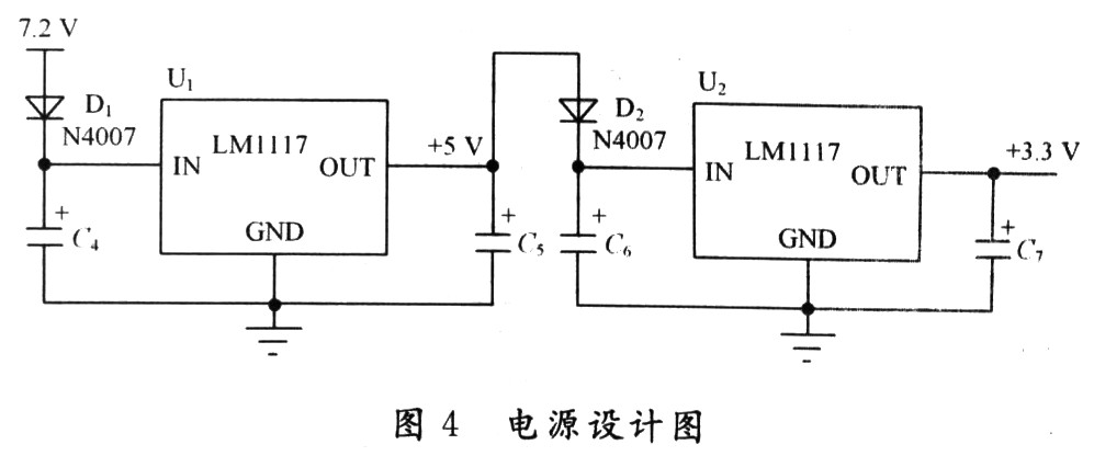
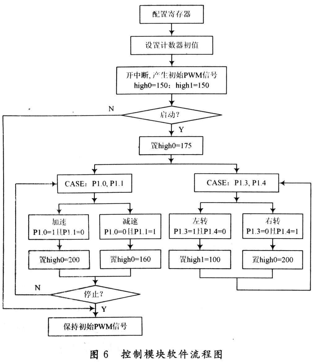
Design of wireless control system for model car based on C8051F040 0 Introduction Automobile durability test is an important part of car test, and the change of driving behavior of test personnel during the test process often leads to inconsistent test results, which reduces the validity of test data. Therefore, major automobile companies have successively used driving robots instead of testers to conduct automobile tests. The use of driving robots for testing is of great significance to reduce the labor intensity of human beings, reduce the harm to the test personnel in the test environment, improve the test efficiency, the objectivity and accuracy of the test results, save the test costs, and then accelerate the progress of automobile research and development. 2 Hardware design, Among them, the resistance value of R1, R2 is half of the radio wave wavelength, which is λ / 2. The inductance values ​​of L1 and L2 are 22 nH and 8.2 nH respectively. They are not only part of the unbalanced transformer, but also provide the required DC bias for the on-chip low noise amplifier (LNA) and power amplifier (PA). The equivalent resistance of the entire antenna system is 50Ω, which meets the requirements of RF input / output matching resistance. 2. 2 hardware design of control module The control module uses the C8051F040 single-chip microcomputer of Silabs as the microprocessor of the system to control the motor and other processing work of the system. The power supply of the system adopts the battery of 7.2 V, and the high level of C8051F040 is 3.3 V, so need to carry on level conversion. This system uses a patch-type LM1117 for level conversion. As shown in Figure 4, because the allowable voltage drop of the input and output of the chip is very small, two LM1117 with different specifications are used to achieve two-level level conversion, and a diode is connected in series in the middle, using the inherent voltage drop of the diode to meet the chip Pressure drop requirements. 3 Software design 3.2 Software design of motor control module The software design flow of this module is shown in Figure 6. After power-on reset, first complete the initialization of the microcontroller, including watchdog initialization, output port definition, crossbar configuration, configuration clock register, T0 clock controller. C8051F040 microcontroller is rich in resources, but based on the 51 core (only 128 special function registers), many of its special function registers cannot be arranged, so a paging mechanism is used. So when configuring different registers, we must first use the selection paging. The interrupt signal is used to generate the PWM signal in the microcontroller, the timing unit is set to 0.01 ms, the initial signal is a period of 16 ms, the high level time is 1.5 ms, high0, high1 respectively control the high level of the speed control waveform and the corner control waveform time. When the start signal is received, P1.0, P1.1 receive the speed signal, P1.3, P1.4 receive the corner signal. Cat6 Sftp Cable,Rj45 Tools,Professional Network Rj45 Tools Dongguan Bofan technology Co., LTD , https://www.ufriendcc.com
In order to test the reliability of driving robots and driving algorithms, there must be a simulated driving system that can meet the requirements of driving robots. The wireless control system of the model car designed in this paper is the main link to realize the simulation driving of the robot, which provides an experimental platform for the driving robot and its driving algorithm.
The system uses a 1:10 electric model car. The speed adjustment is completed by an electronic governor and a brushless DC motor. The steering of the model car is completed through the control of the front wheels by the steering gear. The control signal of the host computer is transmitted to the control core C8051F040 via the ZigBee wireless transceiver module, and the single-chip microcomputer sends the corresponding PWM signal to the electronic governor and steering servo according to the upper-level motion command to realize the control of the model car movement.
1 System framework The system adopts modular design, which is mainly composed of single chip microcomputer, wireless transceiver module, speed feedback, electronic governor, brushless motor, steering servo and host computer. As shown in Figure 1. 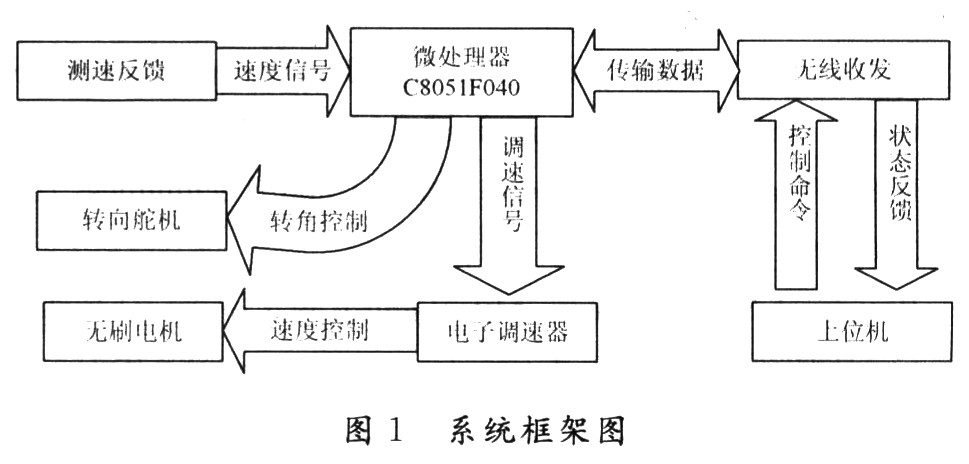
2.1 Hardware design of wireless module The wireless transceiver module realizes the communication between the microprocessor and the host computer through the ZigBee technology, and is the intermediate node between the host computer and the model car motion control module. Through this module, the upper layer control commands can be sent to the microprocessor, and at the same time the microprocessor feeds back the speed signal and the rotation angle signal to the upper layer console.
This module selects the CC2431 chip from TI. CC2431 uses enhanced 8051 MCU, 32/64/128 KB flash memory, 8 KB SRAM and other high-performance modules, and has built-in ZigBee protocol stack and supports 2.4 GHz IEEE 802.15.4 / ZigBee protocol. Figure 2 shows a schematic diagram of the hardware circuit of the wireless module, with CC24.31 chip as the core. The antenna uses an unbalanced antenna. In order to make the antenna work better, an unbalanced transformer should be used to connect the antenna. The unbalanced transformer is composed of resistors R1, R2, inductances L1, L2, capacitor C1 and PCB microwave transmission line. 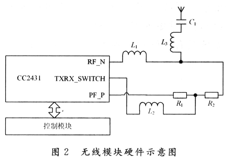
The hardware diagram of the control module is shown in Figure 3 (only the pins used are drawn). The main motor selected a 7.2 V brushless DC motor. Because the commutation of the brushed motor is through the carbon brush and the commutator, but the carbon brush and the commutator will generate sparks when the motor rotates, the carbon powder will cause damage to the component, and the brushless DC motor is commutated by the circuit and Small size and easy to control, so these problems do not exist. The brushless DC motor runs in a self-controlled manner, so it will not add a start winding to the rotor like a synchronous motor that starts under heavy load under variable frequency speed regulation, nor will it oscillate and lose synchronization when the load changes suddenly.
The structure of the brushless DC motor is complicated, so its direct control is realized through the electronic transmission. The on-off time of the MOSFET in the electronic governor is controlled according to the duty cycle of the single-chip PWM signal to control the current, so as to control the motor speed. This method has the advantages of large current and high linearity of output current, which improves the efficiency of the motor.
The steering angle control of the model car is realized with a steering gear. The control of the steering gear is simple, the output torque is large, the output angle is accurate, and the working voltage is low, which is very suitable for the control of the rotation angle of the model car. There is a set of precision reduction gear set inside the servo, and the output of the DC motor is output after the speed reduction of this set of reduction gear. The single-chip microcomputer outputs a PwM signal to control the steering angle of the servo. The signal enters the signal modulation chip inside the servo to obtain a DC bias voltage. The period generated by this DC bias voltage and a standard internal circuit is 20 ms. The width is 1.5 ms. Compare the reference voltage to obtain the voltage difference output. The positive and negative of the voltage difference is output to the motor drive chip to determine the positive and negative rotation of the motor. When the motor speed is constant, the potentiometer is driven to rotate through the cascade reduction gear, so that the voltage difference is 0, and the motor stops rotating. 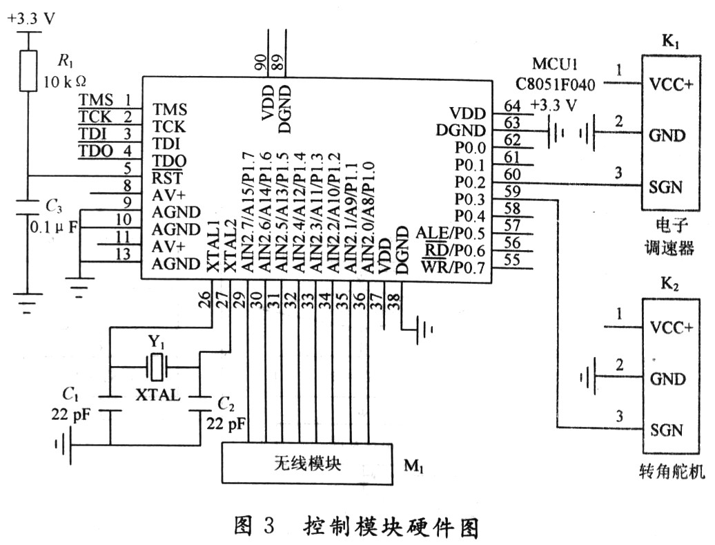
3.1 Wireless module software design The wireless module application program sends the motion control signal of the host computer to the motor control module, and also uploads the motor control quantity of the microprocessor to the host computer. At reset, the system is initialized and interrupts are turned on, the flag bit ST is set, and the system enters sleep mode (ST = 00) after completion. When the host computer has data collection requirements, it communicates with it through the serial port. At this time, the serial port of the system will be triggered to activate the system. Subsequently, the interrupt service program sets the system to send command status (ie ST = 01), first parses the command signal, then packages the command signal and sends it out, and after successful transmission, it will enter the data-waiting mode (ie ST = 10). After that, if data is sent, the bottom layer will transfer the data to the application layer, and then directly upload the data to the host computer through the serial port to complete a data transmission. The program flow is shown in Figure 5. 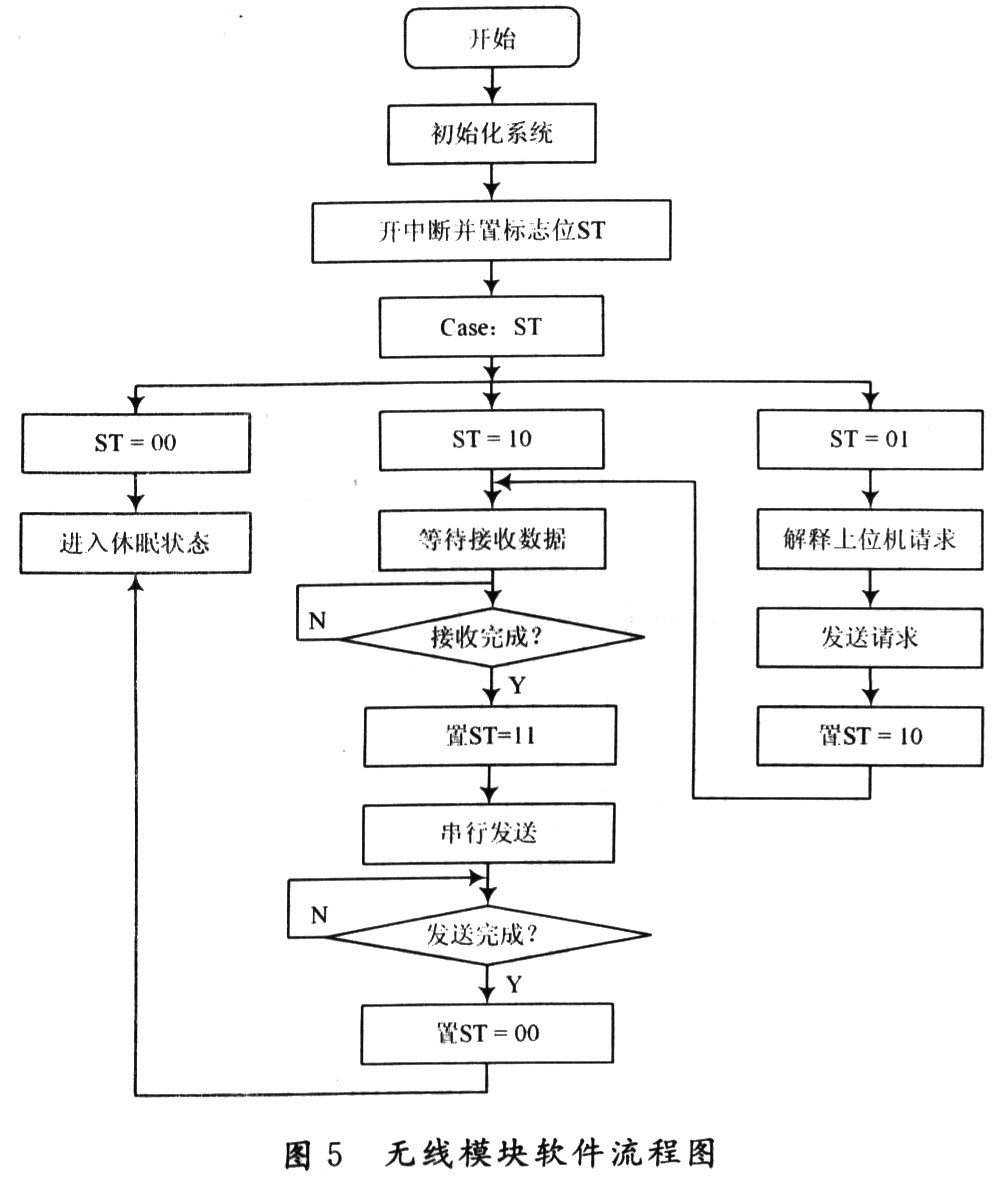
4 conclusions This text has designed the simulation platform taking C8051F040 as the control core, through communicating with the upper computer, can well meet the requirements of robot simulation driving. The system adopts the way of wirelessly controlling the physical model of the host computer, which makes the simulated driving safer and more reliable. The system has good scalability. Through wireless communication, more data acquisition systems can be added to feed back information to the host computer, which expands the application range of the platform. If the positioning feedback system is added, the host computer can shield the movement of the physical model for algorithm simulation and experiment. In terms of parameters, a high-precision measurement feedback system can be added to meet higher simulation requirements by maintaining real-time communication with the host computer.