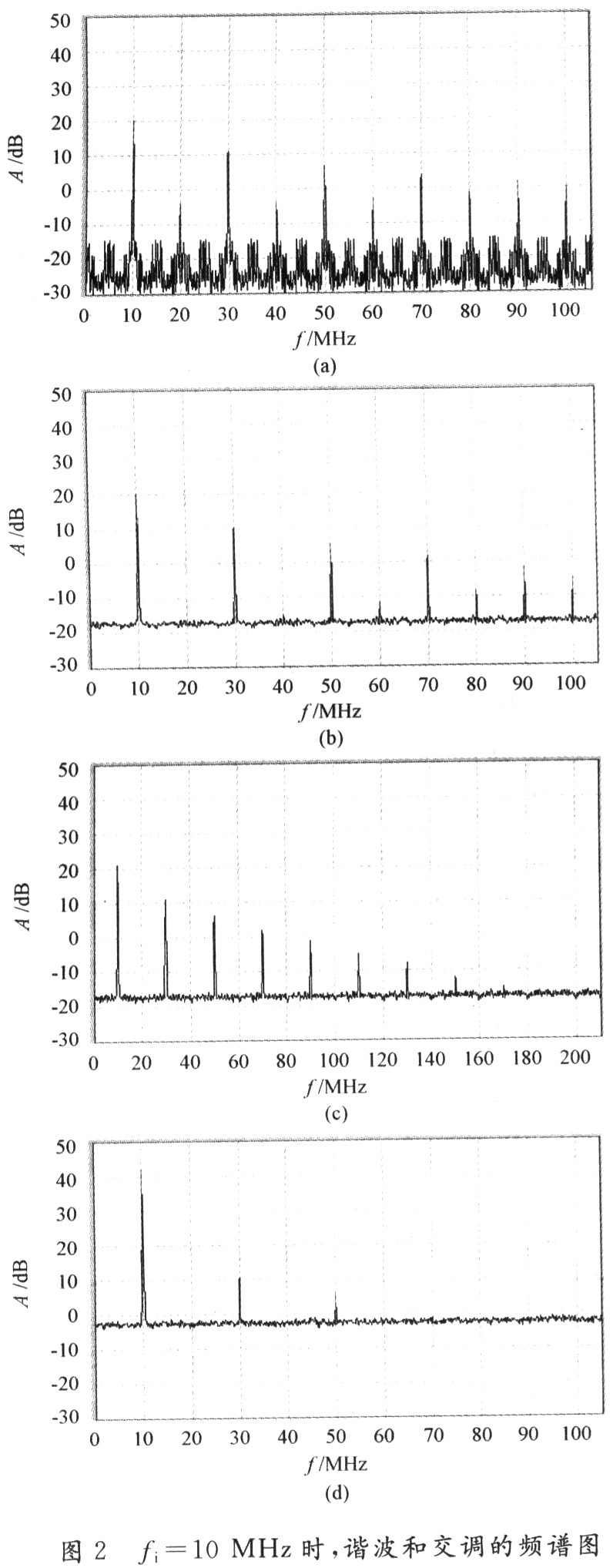
Research on Key Technology Simulation of Digital Radio Frequency Storage System 0 Introduction Digital radio frequency memory (DRFM) is the main component of the active radar jammer in modern electronic countermeasure systems. It is used to accurately copy the received radar signal and then return it to the radar system to confuse the system. It is precisely the characteristics of using DRFM to accurately replicate radar signals. DRFM technology has been widely used in the development of various radar echo signal generators, radar comprehensive testers and various general-purpose signal sources. In order to better reproduce all kinds of signals fidelity, it is the main research content of this article to provide a reliable theoretical basis for the study of digital radio frequency memory. In equation (6), the first term is the harmonic signal of the baseband, which is the spectrum component generated by quantization. Only in the baseband filter, the harmonic will become a parasitic signal, and all terms of nωi> ωs / 2 will be Filter out (n takes an odd number); the second term is completely outside the filter, no need to consider; the third term is the intermodulation signal, all components satisfying (mωs-nωi) <ωs / 2 will become an intermodulation parasitic signal, They are caused by the cross modulation of signal harmonics and clock harmonics. If D represents the duty cycle of the pulse signal and ignores the second term, then equation (6) becomes: The signal generation part uses the Signal Generator module to generate a sine wave; the noise source uses the Gaussian Noise Generator, and the Zero-Order Hold module implements the sampling function. The Compare To Zero module implements single-bit quantization, and the Uniform Encoder module implements multi-bit quantization. Each signal is converted into an appropriate data format by Data Type Conversion and sent to Spectrum Scope to display the spectrum. The model also shows the processed frequency spectrum of four signals, which are generated by the same signal source, to make the results more comparable. In order to simulate the actual environment as much as possible, Gaussian noise with mean 0 and variance 0.01 was added. The results obtained by simulating the model are shown in Figure 2 ((a) to (d) respectively correspond to the four branches of the simulation model). (2) The input signal frequency fi = 20 MHz. Through theoretical analysis and calculation, Table 2 is obtained; the simulation results of the model are shown in Figure 3 ((a) to (d) correspond to the four branches of the simulation model). It can be seen from the theoretical charts and simulation graphics that there is no harmonic generation in this group of simulation schemes, and there is only the fundamental wave at 45 MHz and the intermodulation at 15 MHz and 75 MHz in the spectrum chart. This phenomenon is due to the signal frequency being too high, so that Because the harmonic frequency is too high, it is removed by the baseband filter. Although no harmonics are generated, the power of the intermodulation is very large, which is also a disadvantage to the high-performance operation of the system. Usb3.2 20Gbps Data Cable,Usb 3.2 Type-C,Usb3.2 Type-C Charging Data Cable,High-Speed Usb 3.2 Type-C Dongguan Pinji Electronic Technology Limited , https://www.iquaxusb4cable.com
1 Basic principle The basic working principle of digital radio frequency storage (DRFM): first down-convert the input radio frequency signal to an intermediate frequency signal, and after A / D conversion, it becomes a digital signal, which is written into a high-speed memory. When this signal needs to be retransmitted, this digital signal is read out under the control of the controller and converted into an analog signal by D / A. Then use the same local oscillator for up-conversion to obtain the RF output signal, and complete the storage and forwarding of the input signal.
First analyze the quantization process. Now assume that the baseband input signal is a sinusoidal signal gi (t) = Esinωit and the number of quantization bits is N. The quantized signal can be represented by a step wave y (t), and y (t) can be considered It is the superposition of N pairs of rectangular waves. If the number of quantization bits for the A / D conversion is m, then the number of quantization steps for positive or negative half cycles is N = 2m-1.
The expression of the step wave is: 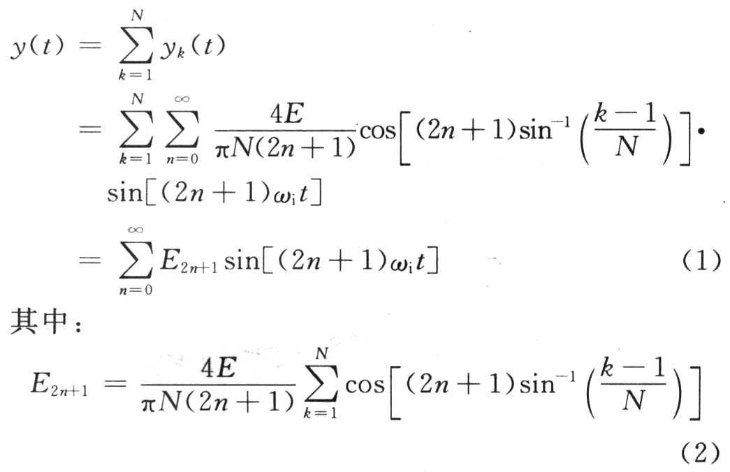
E2n + 1 is the amplitude of the harmonic component generated by quantization. The power of each harmonic can be calculated by this formula.
In the sampling process, for the sake of simplicity, with a quantized signal as input, the input signal is: 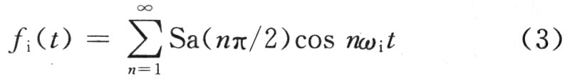
Where: E, ωi are the amplitude and angular frequency of the input signal, respectively. Suppose the sampling pulse signal is fs (t) and the sampled signal is fo (t), then the mathematical expression of the sampling process in the time domain is fo (t) = fi (t) fs (t), which is adopted in DRFM Sampling at equal intervals, the sampling period is Ts, the sampling clock frequency ωs = 2πfs. In the actual circuit, sampling is done at the instant the sampling pulse rises. Therefore, the width of the sampling pulse can be regarded as a narrow pulse width, using τs. To represent. The Fourier series of the sampling pulse is: ![]()
Where: Es, τs, Ts, and ωs are the amplitude, pulse width, period, and angular frequency of the sampled signal, respectively. then: 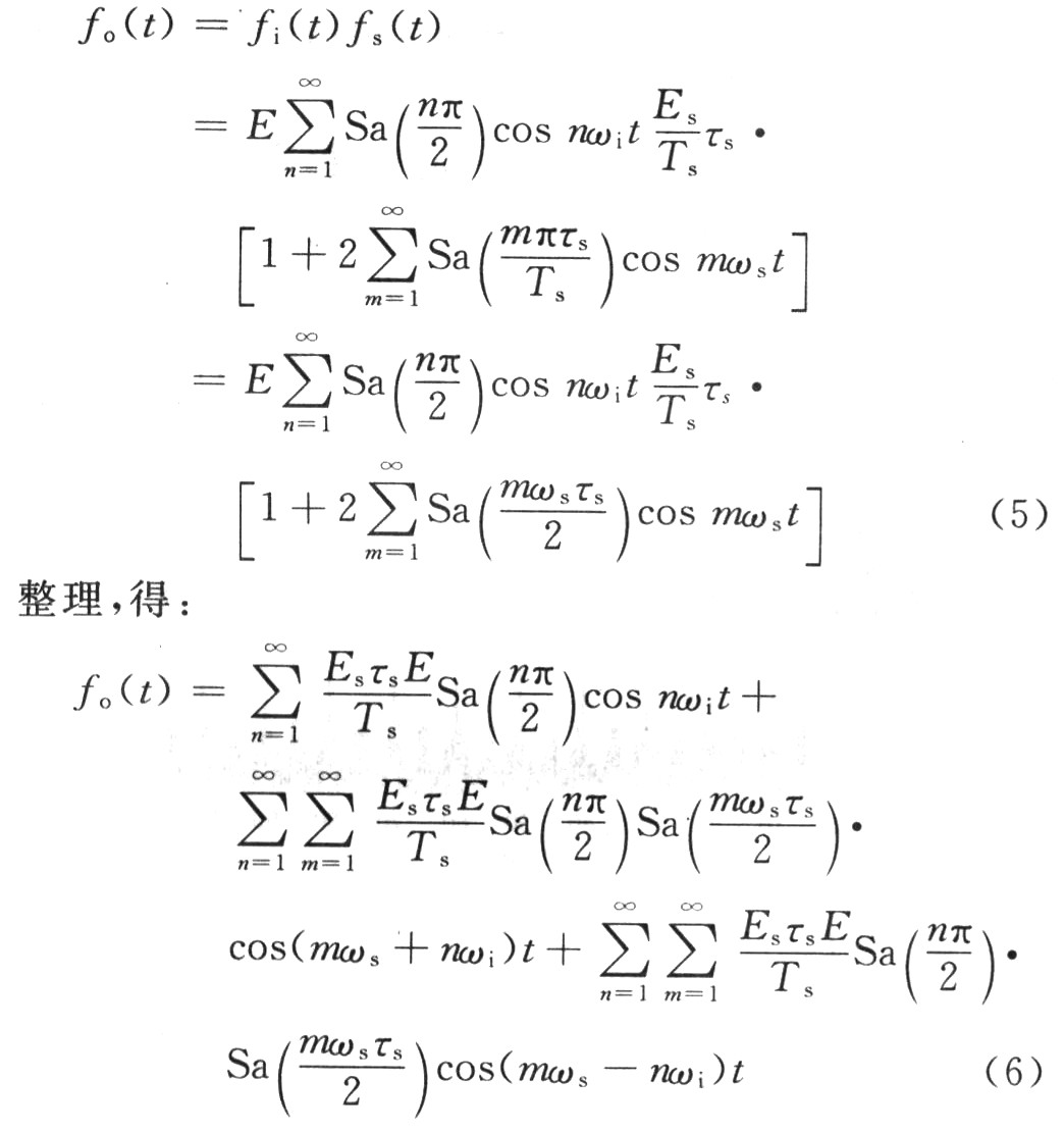
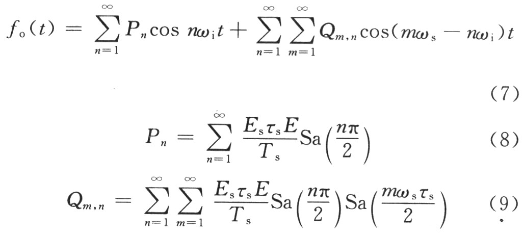
Equation (8) and Equation (9) are the methods to calculate the amplitude of the 1 b quantized DRFM higher harmonic and intermodulation signals.
2 Simulation model By establishing a mathematical model, the Simulink toolbox in the current powerful Matlab can be used to realize the simulation of the system. The simulation modeling of the sampling and quantization process is shown in Figure 1. 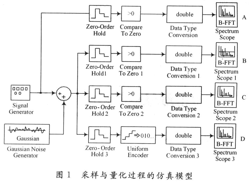
3 Simulation analysis (1) The input signal frequency fi = 10 MHz, and Table 1 is obtained through theoretical analysis and calculation. 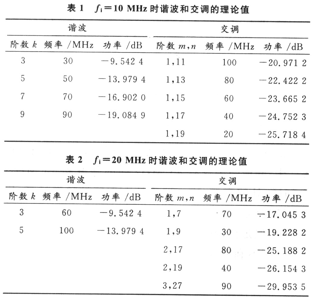
4 Conclusion In summary, according to the sampling and quantization process simulation analysis can be drawn:
(1) Sampling and quantization make the signal spectrum change, and new frequency components-harmonics and intermodulation appear, which reduces the effective transmit power of DRFM and makes the system's working ability worse.
(2) Noise pollution will make the spectrum more complicated. For a system, the output signal-to-noise ratio depends on the input signal-to-noise ratio and the system's internal signal-to-noise ratio. Therefore, the presence of noise will definitely reduce the signal-to-noise ratio of DRFM.
(3) In general, the harmonic component decreases with increasing frequency, while the intermodulation component increases with increasing frequency, that is, the higher harmonic amplitude is lower in the lower order, and the higher order intermodulation amplitude is in the lower order. Big.
(4) When the signal frequency and sampling rate are fixed, increasing the sampling rate or increasing the number of quantization bits can play a role in suppressing parasitic signals. Specifically, increasing the sampling rate has a good suppression effect on intermodulation, but has no obvious effect on harmonics; increasing the number of quantization has a good suppression effect on intermodulation and harmonics.