The BUCK circuit is a step-down chopper, and the output voltage average Uo of the buck converter is always smaller than the output voltage UD. Usually the current in the inductor is continuous, depending on the switching frequency, the filter inductance L and the capacitance C value. BUCK is also a DC-DC basic topology, or circuit structure, which is one of the most basic DC-DC circuits, with DC-to-DC buck conversion. The components used by BUCK and BOOST are mostly the same, but the components are not the same. The output voltage of the simple BUCK circuit is unstable, and it will be interfered by the load and the external. When the PID controller is added, the closed-loop control is realized. The PWM modulated wave can be obtained through the sampling link, and then compared with the reference voltage, and the feedback signal is obtained by the PID controller, and compared with the triangular wave, the modulated switching waveform is obtained, which is used as a switching signal, thereby realizing the closed loop PID control system of the BUCK circuit. . Inductance parameter The choice of inductor is such that the inductor current remains continuous until the minimum specified output current is output. In critical discontinuous operation: and so Capacitance parameter The choice of capacitor must meet the output ripple requirements. Capacitor ripple generation: 1. The ripple generated by the capacitor: relatively small, negligible; 2. The ripple generated by the equivalent inductance of the capacitor: it can be neglected below 300KHZ~500KHZ; 3. Ripple generated by the equivalent resistance of the capacitor: proportional to the current flowing through the esr and the capacitor. In order to reduce the ripple, we must make esr as small as possible. A fast-on transistor is placed between the input and the output, and the average value of the output DC voltage is controlled by adjusting the on-off ratio (duty ratio). The average voltage is composed of square wave pulses of adjustable width, and the average value of the square wave pulse is the DC output voltage. Q conduction: The input power supply supplies power to the load through the switch Q and the inductor L, and simultaneously charges the inductor L. The inductor acts as a constant current source and acts as a transfer of energy. The capacitor is equivalent to a constant voltage source and acts as a filter in the circuit. Q closed: The energy stored in the inductor L continues to supply power to the load R through the loop formed by the freewheeling diode D, thereby ensuring continuous current at the load terminal. It can be seen from the circuit that the inductor L and the capacitor C constitute a low-pass filter. The principle of the filter design is to pass the DC component of us(t) and suppress the passage of the harmonic component of us(t); The output voltage uo(t) on the capacitor is the DC component of us(t) plus the tiny ripple uripple(t). The operating frequency of the circuit is very high. The ripple uripple(t) caused by the charge and discharge of the capacitor in one switching cycle is small. Compared with the DC voltage Uo outputted from the capacitor, the voltage on the capacitor can be regarded as constant at a macroscopic level. When the circuit is in steady state operation, the voltage on the output capacitor is composed of tiny ripple and large DC component. It can be regarded as constant DC in macroscopic view. This is the principle of small ripple approximation in the steady-state analysis of the switching circuit. When the charge of the capacitor is higher than the discharge charge in one cycle, the capacitor voltage rises, resulting in a decrease in the charge charge and a decrease in the discharge charge in the subsequent cycle, which slows the rise of the capacitor voltage, and the process continues until the charge-discharge balance is reached. The voltage remains unchanged; Conversely, if the discharge charge is higher than the charge charge in one cycle, the charge charge will increase in the subsequent cycle, the discharge charge will decrease, and the capacitor voltage drop rate will be slowed down. This process continues until the charge-discharge balance is reached, and the voltage is not maintained. change. This process is a transition process of voltage regulation on the capacitor. When the circuit is in steady state operation, the circuit reaches a stable balance, and the charge and discharge on the capacitor also reaches equilibrium, which is a general rule when the circuit is in steady state operation. When the switch S is placed in the 1st position, the inductor current increases and the inductor stores energy. When the switch S is placed in the 2 position, the inductor current decreases and the inductor discharges energy. Assuming that the current increase is greater than the current reduction, the flux linkage on the inductor during one switching cycle is: ΔΨ=L(Δi)>0 This increment will produce an average induced potential: u=ΔΨ/Τ>0 This potential will reduce the rate of rise of the inductor current and at the same time reduce the rate of decrease of the inductor current, which will eventually result in an average increase in inductor current of zero in one cycle; the same is true for the flux linkage increment on the inductor is less than zero during one switching cycle. The phenomenon that the average increment of the inductor current (average flux linkage increment) is zero in one cycle under steady state conditions is called: inductance volt-second balance. This is another common law in the steady state operation of power electronic circuits. A dramatically more leakproof system. geekvape wenax series box,geekvape wenax series replacement pods,geekvape wenax series mods,geekvape wenax series kit,geekvape wenax series pod kit Ningbo Autrends International Trade Co.,Ltd. , https://www.vapee-cigarettes.com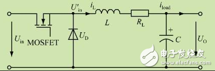
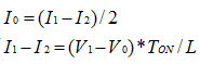
 The larger the current, the smaller the current when entering the discontinuous state.
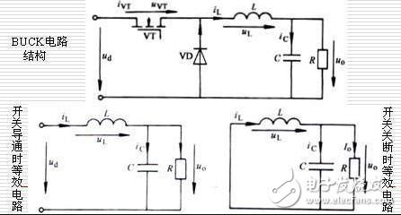
A cartridge so durable, every droplet has nowhere to go.
With a huge leap in battery life with 1000mAh, enjoy a 2-day vape.
New mesh coil, tight and smooth MTL.
All for an enduring vape.
Prevent overheating accidents by pressing the button five times.
After the LED flashes in white, blue, and green in a row, Wenax H1 is
safe to go.
Enjoy three different output levels by simply pressing the firing
button three times.
The LED will indicate the status of the battery and the output
level. All operations are within one button.
Definition of BUCK circuit