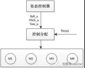
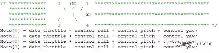
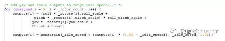
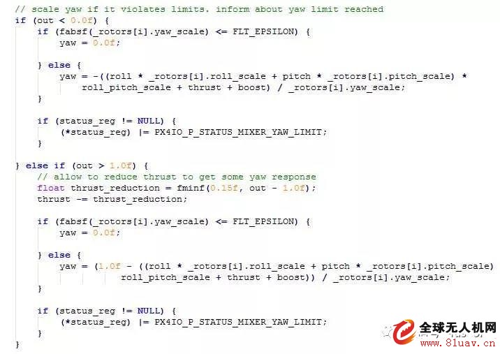
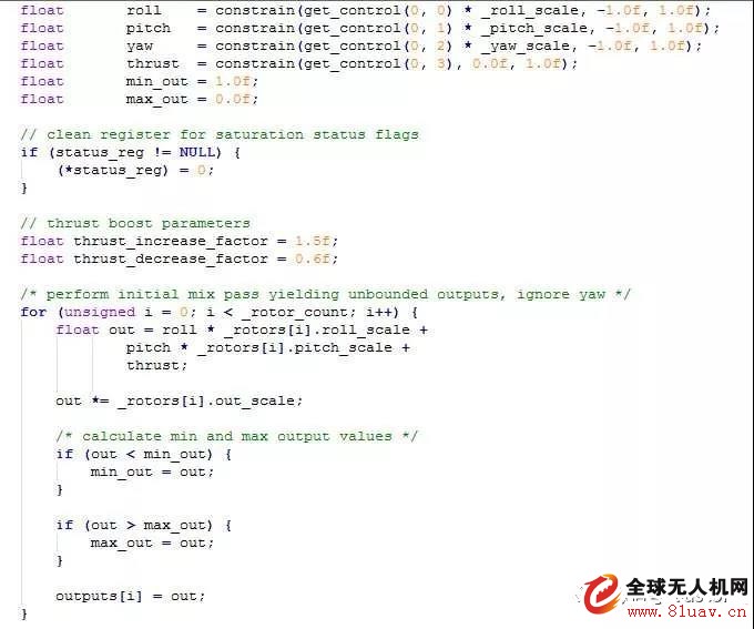
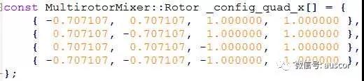
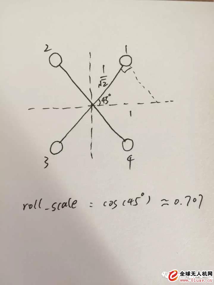
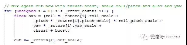
1. What is control allocation? For multi-rotor flight control, the entire control loop is generally layered, such as position control, speed control, attitude control, etc., while the control assignment is responsible for the output obtained by the upper controller (rolling, pitching, yawing Torque), mapped to the actuator, ie the motor, for speed output. Simply put, as follows: 2. What are the benefits of controlling distribution? Ø Separate design control distribution, which can separate the underlying control from the upper control to facilitate the design of the controller; Ø It can prevent the output of the motor from being saturated, as will be discussed later; Ø It can improve the robustness to faults or damages. In simple terms, such as the design of functions such as broken paddle protection, this part is more complicated, this article will not talk about it; 3. Why should we explain the control allocation separately? Control distribution is easy to ignore in engineering applications. I believe that people who have designed flying control software have some experience. This part of the content will not be particularly concerned. The motor output is the addition and subtraction of simple control. This is also possible, can achieve the function, but not good enough, the details need to be optimized, I believe this part is important, and easy to be ignored, when the controller performance is not good, blindly adjust the parameters can not solve the problem of. 4, the following takes the engineering code as an example, step by step logic to push the speech solution: First look at the simplest set Control_roll, control_pitch, and control_yaw are the results obtained by the attitude controller, which represent the three axial control quantities. Here, the throttle value is directly mixed and controlled to obtain the output value of each motor. Seeing this, I believe that some readers have questions about how to determine the amount of control in the code? The most rude way is to try it out, set a symbol, and then look at the actual motor feedback. Of course, this is too low, we are deducting from theory. First, we need to determine the body coordinate system of the aircraft. Assume that the roll control amount is taken as an example. We think that the roll angle roll is left negative right positive. In this case, if the right stroke is made, the target setting is positive, the feedback is 0, and the generated control The quantity is positive. At this time, the 2, 3 motor plus this forward control quantity, 1, 4 minus this forward control quantity, that is, the aircraft flies to the right. In the same way, symbols in other directions are available. Note that the sign of the yaw control amount is related to the clockwise counterclockwise direction of the motor. This simple mixing problem? The first is that the throttle has no limit. It is assumed that the throttle channel output range of the remote control is 1000~2000, and the motor receiving range is 1000~2000. If the throttle is pushed to the maximum during the flight, all the motors are used to respond to the throttle passage. No matter how much the attitude control of your aircraft is, it can't respond, which will cause the aircraft to keep its attitude stable. Improvement one Here, the value of the throttle channel is scaled. The motor responds up to 70% of the throttle. The remaining 30% of the motor is used to respond to the output of the attitude controller to ensure the response margin of the controller. How to join the idle speed of the aircraft? Improvement two As shown in the figure, it is only necessary to add a constant speed value to each motor output. This value is idle speed, generally 10% of the stroke. If set to 0, there is no idle speed. In addition, the proportion of the throttle channel has to be fine-tuned. Written here, this is the control allocation of many open source flight control on the market. It should be noted that: Ø Reasonably distribute the response of the throttle channel and the margin of the attitude control output; Ø The output limit of the attitude controller must be a reasonable range. It is meaningless if it is too large or too small; What are the problems with this control allocation? First of all, it is the output limit of the controller, which is difficult to determine a reasonable range; Secondly, when the throttle is at the lowest, if the outer eight/inner eight lock operation is performed, the aircraft is easy to turn over, and the motor output is used to maximize the response to the yaw control. The intuitive phenomenon is that the diagonal motor speed varies greatly, and even the motor stops; In addition, in extreme cases, such as the three axial control is very large, the generated motor output exceeds the maximum value, for example, 2200, can not give priority to the response of the attitude control amount; this situation requires the throttle or Scale the attitude control to ensure that the output is within range. There are still some details related to it. For example, only the yaw rod is used. In theory, the aircraft should rotate around the axis. However, many of them are flying in a circle. Of course, the main problem lies in attitude control, but it is also related to control distribution. If the speed of the rod is fast, the amount of control generated by yaw Very large, there is not enough margin in the roll and pitch directions to respond. Promoted to six or eight axes, if one of the motors does not turn, can it fly smoothly? The answer is that this method of control distribution is more prone to problems. The short answer is that there is a motor stall, and the speed assigned to other motors is increased, which makes it easy for the motor to saturate. Of course, if the output of the motor itself is not saturated, it can continue to fly stably. in conclusion: A good control allocation algorithm should at least be solved: If the throttle control is too large and too small, it can have sufficient attitude control margin to ensure flight stability. In short, it is necessary to be able to increase and decrease the amount of throttle according to the size of the motor output, and to scale the attitude control amount. Take pixhawk's control allocation algorithm mixer as an example: Algorithm steps: Regardless of the yaw control, only the roll, pitch and throttle are combined. Get the maximum and minimum output of the motor. Insert a knowledge point: The _roll_scale variable in the code is based on the geometry of the aircraft, taking a four-axis X shape as an example. Similarly, picth_scale and yaw_scale are calculated. Then, according to the maximum and minimum output of the motor, the attitude scaling value roll_pitch_scale and the change amount of the throttle amount boost are calculated. After the throttle and attitude are mixed, add yaw and calculate again. If yaw is added, the motor output is saturated and yaw is scaled. Finally, the scaled yaw and idle speed are added to get the final motor output. Here is not to publicize the code, master the main ideas.
Water-cooled capacitor is supercapacitor is a capacitor with a capacity of thousands of farads.According to the principle of capacitor, capacitance depends on the distance between the electrode and electrode surface area, in order to get such a large capacitance, as far as possible to narrow the distance between the super capacitor electrode, electrode surface area increased, therefore, through the theory of electric double layer and porous activated carbon electrode.
Water-Cooled Capacitor,Water-Cooled Power Capacitor,Water-Cooled Electric Heat Capacitor,Water-Cooled Electric Heating Capacitor YANGZHOU POSITIONING TECH CO., LTD. , https://www.yzpst.com