Some time ago, I helped a friend to repair a lot of elevator electronic boards, including the door board, code board, I/O board, main control board, call-to-call communication board and display board. It was slightly smaller and was written to share with you. . Its ruggedized structure and Fashion is Slim and Light performance ensure the monitor can work stable at harsh environmental conditions. Monitor`s front bezel is made of White/Black powder coated aluminum. We provide vandal-proof protective glass or touch-screen for covering the front screen. Also we have various boards for different signal input solutions, and 12V/24V DC power input for different application requirements. medical monitoring,monitor medical,medical monitors,medical lcd monitor,medical display monitor,medical displays Shenzhen Hengstar Technology Co., Ltd. , https://www.angeltondal.com
Electronic boards commonly used in elevators can generally be divided into the following modules: 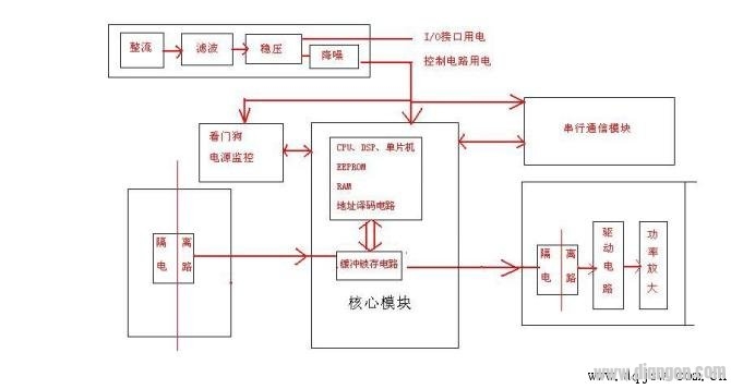
1. The power module generally includes a rectifier circuit, a voltage stabilization circuit, a filter circuit, and a power supply monitoring circuit;
2, the core processing module, including CPU (or microcontroller, DSP processor), EEPROM, RAM, address signal decoding circuit, oscillation circuit, reset circuit, watchdog circuit;
3, signal input module: including buck circuit, signal isolation circuit (usually using optical and micro-transformers), buffer latch circuit;
4, signal output module: including buffer latch circuit, signal isolation circuit (usually using optical and micro-transformers), power amplifier circuit.
5. Serial communication module: The serial communication technology used in the elevator is mainly RS232, RS485 or CAN bus. RS232 is used for connection with debugger and computer. Internal communication generally adopts RS485 or CAN bus technology.
In various electronic boards in the elevator, the core components are less likely to be damaged under normal use. Because the processor, EPROM, RAM, crystal oscillator, etc. all operate at 5V or lower, it is purely a binary signal. The fault is usually in the I/O interface section and the power section. For example, the input aperture, the aperture current limiting resistor, the output part of the power amplifier transistor, the thyristor and the driver circuit. The power supply part mainly has no voltage, low voltage, and too much power fluctuation.
Before repairing the electronic board, be sure to ask the fault phenomenon in detail to understand the role of the relevant interface, which can shorten the time required to judge the fault. The electronic board must be carefully designed. If the signal is not understood, the signal should not be shorted to avoid further expansion.
I am in the maintenance of the electronic board, generally as follows:
1. First, check whether the electronic board starts the basic initialization operation. The easiest way to determine whether the motherboard is initialized is to check whether the output relay is closed, whether the LED display is normal, and whether there is an error. If there is an alarm sound, there are numbers or characters, it is basically judged that the core processing module is normal.
If it is not normal, first check whether the external input voltage of the motherboard is normal and the current is normal. After confirming that the power is normal, you can check whether the voltage of the CPU is normal (usually 5V), whether the reset circuit is normal, and whether the oscillation circuit is normal.
In my experience board, I have encountered many failures caused by reset circuit protection. The reset circuit protection is generally caused by intermittent operation or holding action of the watchdog circuit due to the low core voltage. Please note that the core voltage refers to the voltage that the input power supply passes through the rectifier circuit, the voltage regulator circuit, the filter circuit, and the core module such as the CPU after the power monitor circuit. It is not the external input voltage. And the required precision is relatively high, the circuit such as CPU should not be lower than 4.6V, and the watchdog should not be lower than 5V (the circuit design is different, for reference only).
2. Maintenance method without reflection after inputting the signal: first confirm whether the power supply is normal and determine whether the CPU is working normally. In the case of such a fault, generally check the input circuit interface section to check whether the protection diode and the current limiting resistor are broken down, and whether the diaphragm and the isolation transformer are normal. In a circuit with a stop, the latch circuit is substantially not damaged. Therefore, the optocoupler can be used as a dividing line to judge whether the fault occurs at the front end or the back end of the diaphragm.
Method: You can directly input the corresponding voltage at the input end of the diaphragm, let the diaphragm move, check whether the electronic board has a corresponding reflection. If there is any reflection, it can be judged that there is a problem with the previous circuit of the diaphragm. If there is no corresponding reflection, a 5V voltage can be connected to a 470 ohm resistor and directly input to the output end of the diaphragm, and then check whether the electronic board has a corresponding reflection;
3. Maintenance method without output signal: first confirm whether the power supply is normal, determine whether the CPU is working normally, and check whether the corresponding input signal is normal. After confirming the above, the power amplification interface circuit, the power component driving circuit, the signal isolation circuit (optical or transformer), and the signal latch circuit of the output interface are sequentially checked.
4, communication is not normal:
In principle, a communication node error does not affect the entire communication network. However, in practical applications, due to program design and hardware design reasons, a node error will cause the entire communication to be abnormal, and the call may not be normal. Strange phenomena such as display, opening and closing, etc. At present, I still can't eat CAN bus technology, I can only write my own experience, for reference only. For example, an elevator maintained by our company adopts Xinshida serial communication board and 13-story station. During the first half of use, the door machine frequently keeps opening the door for a long time without closing the door. The signal cannot be registered, the display is abnormal, and the power is turned off after the power is turned off. The elevator returned to normal and the same fault occurred repeatedly after a period of use. After checking one of the external call boards is not normal, because this phenomenon is unstable, I replaced all the above power supply filter capacitors, and then did not appear the same fault.
Due to personal technical skills and experience limitations, please do not hesitate to take advantage of it.